AMX MSA-MMK2-07 Handleiding


Lees hieronder de đź“– handleiding in het Nederlandse voor AMX MSA-MMK2-07 (2 pagina's) in de categorie Niet gecategoriseerd. Deze handleiding was nuttig voor 15 personen en werd door 2 gebruikers gemiddeld met 4.5 sterren beoordeeld

Pagina 1/2
QUICK START GUIDE
MSA-MMK/2-xx Multi Mount Kits for Wall Mount
Modero S Series Touch Panels & AMX RoomBook Scheduling Panels
MSA-MMK/2 Multi Mount Kits
The MSA-MMK/2-xx Multi Mount Kits are designed to mount Modero S Series Wall
Mount Touch Panels and AMX RoomBook Scheduling Panels to any smooth surface
without drilling or cutting, enhancing the beauty and functionality of glass, marble and
stone architecture with the sleek style of an AMX control interface (FIG. 1).
Models Available/Panel Compatibility
There are several versions of the Multi Mount Kits available to accommodate both
Modero S Series and AMX RoomBook Scheduling Touch Panels:
“MMK2” Multi Mount Kits
The MSA-MMK2-10 and MSA-MMK2-07 Multi Mount Kits are intended for use with
second-generation “-L2” Modero S Series (Landscape/Wall Mount), as well as all AMX
RoomBook Scheduling touch panels.
Note that the installation procedure for the second-generation MMK2 versions of the
kits is essentially the same as the first-generation MMK kits, with only a minor change
to the top hook design.
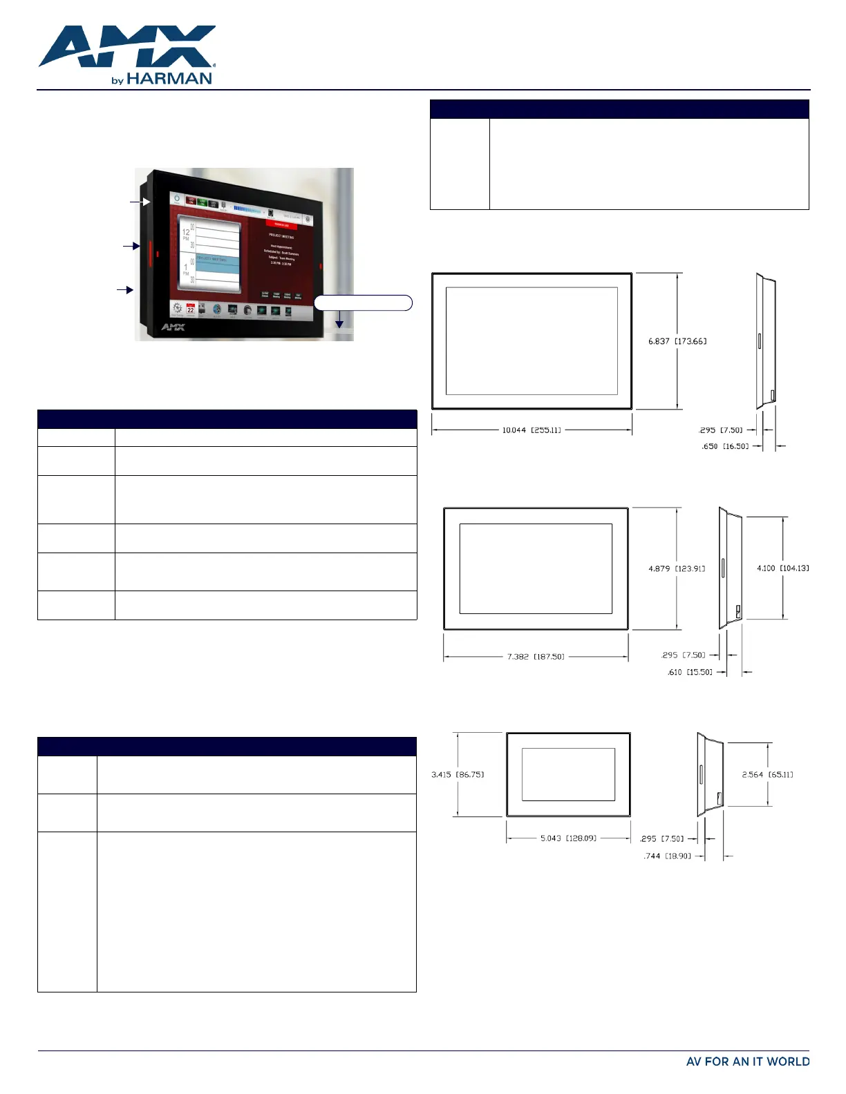
Product Specifications
Dimensions
MSA-MMK/2-10
FIG. 2 provides the dimensions of the MSA-MMK-10 and MSA-MMK2-10:
MSA-MMK/2-07
FIG. 3 provides the dimensions of the MSA-MMK-07 and MSA-MMK2-07:
MSA-MMK-43
FIG. 4 provides the dimensions of the MSA-MMK-43:
Surface Preparation
Since the Multi Mount Kits are designed to be installed onto smooth surfaces, special
considerations must be made to prepare the surface. Before installation, place the back
of the Back Box to the surface and verify the final placement of the Multi Mount Kit and
touch panel.
The Back Box should not be placed anywhere where it may interfere with foot traffic or
with the operation of doors or other items in the immediate environment.
The surface where the Multi Mount Kit needs to be installed should be cleaned with
alcohol or another solvent that will not damage the surface, and then allowed to dry
fully before the Multi Mount Kit is installed.
Note: Do not touch the installation area or the tape strips with bare hands, as skin oil
from your fingers may interfere with adhesion of the tape used for installation.
FIG. 1 MSA-MMK MULTI MOUNT KIT (EXAMPLE INSTALLATION)
MODELS AVAILABLE/PANEL COMPATIBILITY:
Multi Mount Kit For use with:
MSA-MMK-10
(FG2265-11)
• MSD-1001-L (FG2265-01): 10.1" Modero S Series Landscape Wall
Mount Touch Panel
MSA-MMK2-10
(FG2265-21)
• MSD-1001-L2 (FG2265-31): 10.1" Modero S Series Landscape Wall
Mount Touch Panel
• RMBK-1001 (FG2265-40): 10.1” AMX RoomBook Scheduling Touch
Panel
MSA-MMK-07
(FG2265-12)
• MSD-1001-L (FG2265-01): 10.1" Modero S Series Landscape Wall
Mount Touch Panel
MSA-MMK2-07
(FG2265-22)
• MSD-701-L2 (FG2265-32): 7" Modero S Series Landscape Wall Mount
Touch Panel
• RMBK-701 (FG2265-37): 7” AMX RoomBook Scheduling Touch Panel
MSA-MMK-43
(FG2265-13)
• MSD-431-L (FG2265-03): 4.3" Modero S Series Landscape Wall Mount
Touch Panel
PRODUCT SPECIF ICATIONS
Dimensions
(HWD):
•MSA-MMK/2-10: 6.84” x 10.04” x 0.95” (17.37cm x 25.51cm x 2.40cm)
•MSA-MMK/2-07: 4.88” x 7.38” x 0.91” (12.39cm x 18.75cm x 2.25cm)
•MSA-MMK-43: 3.42” x 5.04” x 1.04” (8.68cm x 12.81cm x 2.64cm)
Weight: • MSA-MMK/2-10: 0.25 lbs (113.40 g)
•MSA-MMK/2-07: 0.10 lbs (45.36 g)
•MSA-MMK-43: 0.03 lbs (22.68 g)
Included
Accessories:
MSA-MMK/2-10:
• Back Box (60-2265-11)
• Modero S Multi Mount Cable Cover (2) (60-2265-32)
• Ethernet Cable, Clear, with 8-pin Flat Connector (ECA2265-02)
• UTP CAT.5E Black Snap-In Coupler (64-5968-01)
• Tape, Double-Sided (66-2265-25)
• HPG-10 HydraPort .75-Inch Grommet (FG570-10)
MSA-MMK/2-07:
• Back Box (60-2265-12)
• Modero S Multi Mount Cable Cover (2) (60-2265-32)
• Ethernet Cable, Clear, with 8-pin Flat Connector (ECA2265-02)
• UTP CAT.5E Black Snap-In Coupler (64-5968-01)
• Tape, Double-Sided (66-2265-25)
• HPG-10 HydraPort .75-Inch Grommet (FG570-10)
MSA-MMK
Multi Mount Kit
Mounting surface
Modero S Series
Touch Panel
Clear Ethernet cable
PRODUCT SPECIF ICATIONS (CONT.)
Included
Accessories:
MSA-MMK-43:
• Back Box (60-2265-13)
• Modero S Multi Mount Cable Cover (2) (60-2265-32)
• Ethernet Cable, Clear, with 8-pin Flat Connector (ECA2265-02)
• UTP CAT.5E Black Snap-In Coupler (64-5968-01)
• Ferrite (04-0052)
• Tape, Double-Sided (66-2265-25)
• HPG-10 HydraPort .75-Inch Grommet (FG570-10)
FIG. 2 MSA-MMK/2-10: DIMENSIONS
FIG. 3 MSA-MMK/2-07: DIMENSIONS
FIG. 4 MSA-MMK-43: DIMENSIONS
© 2016 Harman. All rights reserved. Modero, Modero S Series, AMX, AV FOR AN IT WORLD, HARMAN, and their respective logos are registered
trademarks of HARMAN. Oracle, Java and any other company or brand name referenced may be trademarks/registered trademarks of their
respective companies.
AMX does not assume responsibility for errors or omissions. AMX also reserves the right to alter specifications without prior notice at any time.
The AMX Warranty and Return Policy and related documents can be viewed/downloaded at www.amx.com.
3000 RESEARCH DRIVE, RICHARDSON, TX 75082 AMX.com | 800.222.0193 | 469.624.8000 | +1.469.624.7400 | fax 469.624.7153
AMX (UK) LTD, AMX by HARMAN - Unit C, Auster Road, Clifton Moor, York, YO30 4GD United Kingdom • +44 1904-343-100 • www.amx.com/eu/
93-2265-12 REV: D
Last Revised: 3/31/2016
Multi Mount Kit Installation
After determining the exact location where the Multi Mount Kit is to be installed, the
Back Box may be attached to the mounting surface. To install the Back Box:
1. Each Multi Mount Kit comes with two sets of strips of adhesive tape, attached to
the back of the Back Box (FIG. 5). Carefully peel the backing from the tape strips.
2. Press the back of the Back Box to the installation surface. Make sure that the
positioning is correct, because the tape cannot be removed and then reapplied.
3. Pull enough slack on the clear Ethernet cable through the Back Box to allow the
cable to reach the touch panel’s RJ45 connector.
4. Remove the touch panel’s back box to access the back of the panel.
5. Insert each connector into its corresponding location along the back of the touch
panel.
Note: For more information on connection, please refer to the Operation Reference
Guide for the Modero S Series panel being installed, available from www.amx.com.
6. Test the incoming wiring by attaching the panel connections to their terminal
locations and applying power. Verify that the panel is receiving power and
functioning properly to prevent repetition of the installation.
7. Latch the panel onto the top hooks on the back box and rotate it down. Press
gently but firmly and evenly on the surface of the touch panel until the top panel
snap “clicks” to lock it down.
WARNING: if you see a gap between the panel and the Back Box, or feel any
binding while locking down the panel, stop immediately and verify that no
cables or other items are in the way. Do not force the panel into position, as this
can cause damage to the touch screen or the panel electronics.
8. Peel the backing from one side of the double-sided tape (66-2265-25) and attach
it to the side of the clear Ethernet cable facing the wall surface, as close to the
side of the back box as possible.
9. Peel the remaining backing from the double-sided tape and press the cable firmly
and evenly against the wall surface to secure the cable.
10. Draw up any remaining slack in the clear Ethernet cable, so that only the absolute
minimum cable necessary is visible.
11. Slide the grommet down the clear Ethernet cable and into the cable hole in the
wall to conceal the hole.
12. Reconnect the terminal Ethernet to its respective location on the NetLinx Master.
Ethernet/RJ-45 Connections and Wiring
The Ethernet cable connecting the touch panel to the network should have the
minimum amount visible across the surface when installation is finished. The total
length of the cable is 2 meters (6.56 feet).
To prepare the Ethernet cable for installation:
1. Examine the area for the nearest available wall through which Ethernet cable
connected to the Master can be drawn, and draw the cable to the location.
2. Remove the Multi Mount Cable Cover (60-2265-32) on the Back Box closest to the
available wall (FIG. 1), and pass the clear Ethernet cable through the end cap hole.
Make sure that the end of the cable with the ferrite attached is outside the Back
Box when you are finished.
3. Drill a 3/4” hole through the wall surface nearest to the installation surface to
allow the clear Ethernet cable (ECA2265-02) to pass through. Pull the main
Ethernet cable through the hole to the installation surface.
4. Snap both halves of the HydraPort Grommet (FG570-10) to the terminal end of
the clear Ethernet cable, with the pointed end of the grommet facing the wall.
Make sure that the grommet is installed between the ferrite and the Back Box.
5. Connect the terminal end of the clear Ethernet cable to the main Ethernet cable,
using the snap-in male-to-male coupler (64-5968-01).
Do NOT draw up the slack until the clear Ethernet cable is connected to the touch
panel.
Ethernet RJ-45 Pin-outs and Signals
The following table lists the pin-outs, signals, and pairing for the Ethernet connector.
Uninstalling the Touch Panel
In order to access the back of the touch panel, such as to install a USB connection for
firmware upgrades, the device may need to be uninstalled from the Back Box. To
uninstall the touch panel:
1. From the bottom, pull gently outward from the back box. Gently rock the panel
back and forth to free the bottom from the back box.
2. Rotate it up to release the top latch hooks, and carefully pull the device free from
the back box. Take care not to damage or pull the connections on the back of the
device, or to pull the Multi Mount Kit back box from the installation surface.
Additional Documentation
The following related product documents are available to view/download at
www.amx.com:
• For information on installing and configuring AMX RoomBook Scheduling Touch
Panels, refer to the AMX RoomBook Scheduling Touch Panels Instruction Manual.
• For information on installing Modero S Series Touch Panels, refer to the Modero S
Series Touch Panels Installation Hardware Reference Manual.
• Specification drawings of the MSA-MMK/2 Multi Mount Kits.
FIG. 5 PLACEMENT OF ADHESIVE TAPE ON THE BACK BOX
Horizontal tape
Horizontal tape
Vertical tape
Vertical tape
ETHERNET RJ-45 PIN-OUTS AND SIGNALS
Pin Signals Connections Pairing
1 TX + 1 --------- 1 1 --------- 2
2 TX - 2 --------- 2
3 RX + 3 --------- 3 3 --------- 6
4 PoE power 4 --------- 4
5 PoE power 5 --------- 5 4 --------- 5
6 RX - 6 --------- 6
7 PoE power 7 --------- 7 7 --------- 8
8 PoE power 8 --------- 8
FIG. 6 RJ-45 WIRING DIAGRAM


Product specificaties

Merk: AMX
Categorie: Niet gecategoriseerd
Model: MSA-MMK2-07

Heb je hulp nodig?

Als je hulp nodig hebt met AMX MSA-MMK2-07 stel dan hieronder een vraag en andere gebruikers zullen je antwoorden


Handleiding Niet gecategoriseerd AMX

Handleiding Niet gecategoriseerd

Nieuwste handleidingen voor Niet gecategoriseerd