AMX HPX-AV100-RGB+A Handleiding
AMX Niet gecategoriseerd HPX-AV100-RGB+A
Bekijk gratis de handleiding van AMX HPX-AV100-RGB+A (2 pagina’s), behorend tot de categorie Niet gecategoriseerd. Deze gids werd als nuttig beoordeeld door 109 mensen en kreeg gemiddeld 4.8 sterren uit 2 reviews. Heb je een vraag over AMX HPX-AV100-RGB+A of wil je andere gebruikers van dit product iets vragen? Stel een vraag
Pagina 1/2
QUICK START GUIDE
HPX-AV100-RGB+A Hydraport RGB AV Module
Overview
The HPX-AV100-RGB+A Hydraport Composite AV Module (FG552-11) is designed to be
used in conjunction with the HPX-1600 Hydraport Base Assembly. See specifications
for module requirements. For more information on the HPX-1600, refer to
www.amx.com.
The HPX-AV100-RGB+A provides user-accessible RGB (VGA HD-15) Video and Stereo
connections on the face of the Hydraport system. The HPX-AV100-RGB+A provides
connection from the user's source equipment to a remote client such as projector,
monitor, display or stereo sound system.
Product Specifications
Installation
Important!Only a professional, AMX-qualified installer should perform this installation.
Installation must conform to all local codes. This product may not be installed by the
end-user.
Tools Required
•Wire cutting pliers
•Wire strippers
•Small flat blade screw driver
•Phillips Screw Driver (to access Hydraport Base Assembly)
CAUTION! Ensure that the AC Power cord is disconnected from IEC C-14 power inlet
connector on the Hydraport Base Assembly prior to disassembly of the Hydraport Base
assembly or installation of the HPX-AV100-RGB+A Module (see FIG.2).
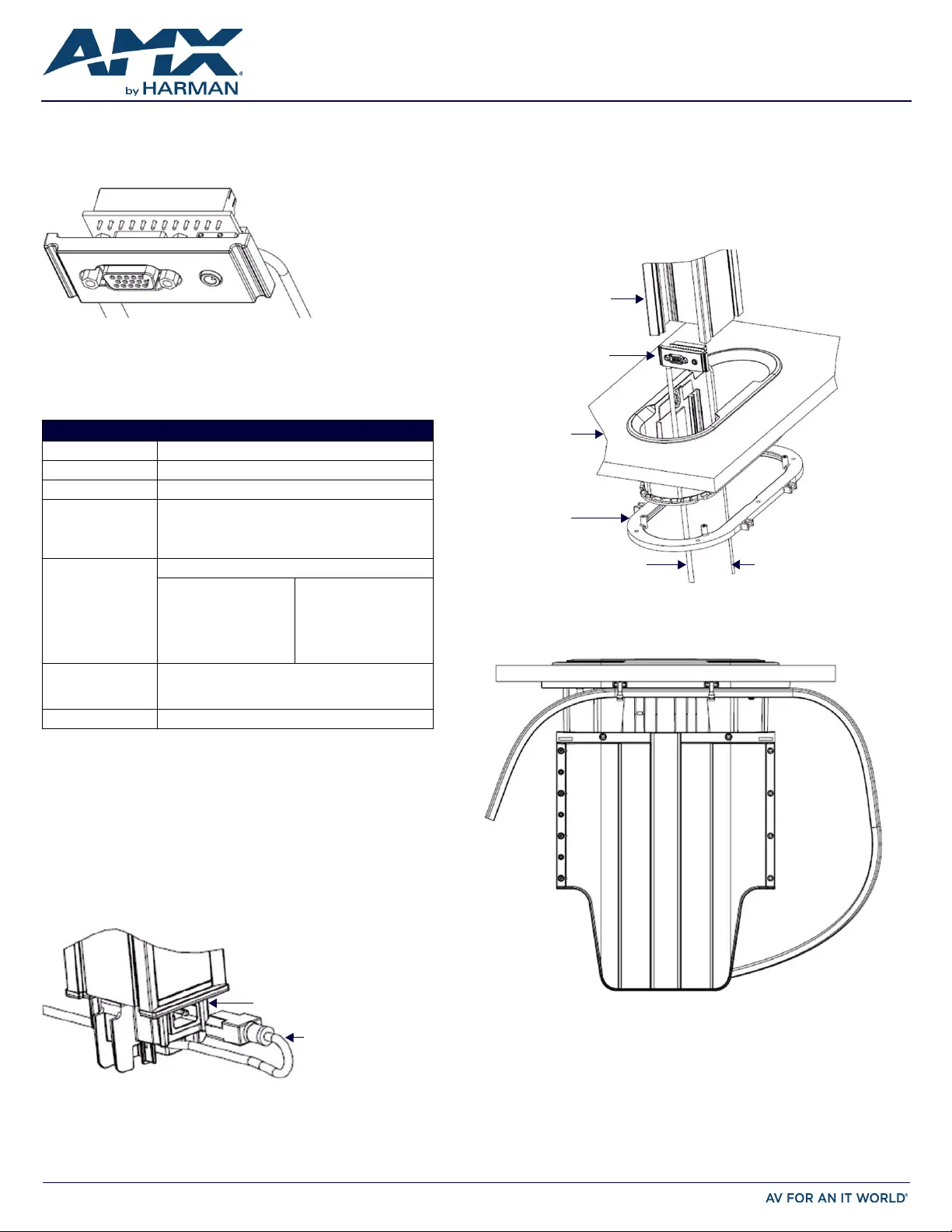
Step 1 - Backside Termination
Before installing the module into the Hydraport Base Assembly, the backside
terminations of the module must be completed. This backside termination requires
connecting three coaxial cables (or equivalent) to the 6 position phoenix terminal block
located on the back of the module.
Note that for terminations for which the far end of the cable is not accessible either
because the cable has been run under carpet, in a conduit or structure, or is otherwise
fixed, the cable must be placed through the retaining ring (note the orientation of the
retaining ring) then through the mounting surface from bottom to top, then to the
module - before the module is placed into the base assembly (FIG.3).
Step 2 - Provide a Service Loop
Ensure there is sufficient cable length to provide a service loop for the cable after the
module is installed into the Hydraport Base Assembly (FIG.4).
Note that the Hydraport Base Assembly travels up and down approximately 228.6 mm
(9”) during operation.
The service loop must accommodate this motion and provide for securing the cable to
the Hydraport Base Assembly for strain relief.
For more detailed information, please refer to the HPX-1600-XX Hydraport Base
Assembly Instruction Manual.
FIG. 1
HPX-AV100-RGB+A COMPOSITE AV MODULE
HPX-AV100-RGB+A SPECIFICATIONS
Dimensions (HWD)25mm x 52mm x 25mm (0.98” x 2.05” x 0.98”)
Weight:31 g (1.09 oz.)
Enclosure:Matt black finished face plate (Polycarbonate plastic).
Front Connections:HD-15 RGB (VGA) style connections for:
•RGB Video (VGA)
•Left Audio
•Right Audio
Rear Connections:12 Position Phoenix terminal block with connections for:
•Left Audio Signal +
•Right Audio Signal +
•Audio Ground -
•Horizontal Sync +
•Vertical Sync +
•Sync Ground -
•Red Video Signal +
•Red Video Ground -
•Green Video Signal +
•Green Video Ground -
•Blue Video Signal +
•Blue Video Ground -
Compatibility:•HPX-1600 Hydraport Base Assembly
•D-Sub HD-15 RGBHV (VGA) Video Source
•3.5mm Jack style Stereo Audio Source
Included Accessories:Installation Guide
FIG. 2 HPX-1600 - POWER INLET CORD REMOVED
AC Power Cord
Power Inlet Connector
on HPX-1600
FIG. 3 FIXED CABLE PASSING THROUGH RING, TABLE AND INTO THE HPX-1600 CHASSIS
FIG. 4 SECURED SERVICE LOOP
Module
Fixed cables pass-through
Retaining Ring, Surface
to Module
Fixed cables pass-through
Retaining Ring, Surface
to Module
Retaining Ring
Mounting Surface
HPX-1600 Chassis
Product specificaties
| Merk: | AMX |
| Categorie: | Niet gecategoriseerd |
| Model: | HPX-AV100-RGB+A |
Heb je hulp nodig?
Als je hulp nodig hebt met AMX HPX-AV100-RGB+A stel dan hieronder een vraag en andere gebruikers zullen je antwoorden
Handleiding Niet gecategoriseerd AMX

10 Mei 2026
7 Mei 2026
5 Mei 2026
4 Mei 2026
24 November 2025
5 Augustus 2025
5 Augustus 2025
4 Augustus 2025
4 Augustus 2025
4 Augustus 2025
Handleiding Niet gecategoriseerd
Nieuwste handleidingen voor Niet gecategoriseerd
8 Juni 2026
8 Juni 2026
8 Juni 2026
8 Juni 2026
8 Juni 2026
8 Juni 2026
8 Juni 2026
8 Juni 2026
8 Juni 2026
8 Juni 2026